Configuring VTP Transparent Mode on Cisco Catalyst Switches
Objective
The objective of this lab exercise is to learn and understand how to configure VTP Transparent mode on Cisco Catalyst Switches. By default, all Cisco switches are VTP server devices.
Purpose
Configuring VTP Transparent mode is a fundamental skill. VLANs configured on a switch in VTP Transparent mode are not automatically propagated to other switches within the same VTP domain as they would be by a VTP server. Switches configured in VTP Transparent mode use a trunk to forward traffic for configured VLANs to other switches. As a Cisco engineer, and for the Cisco CCNA exam, you will be expected to know how to configure VTP Transparent mode.
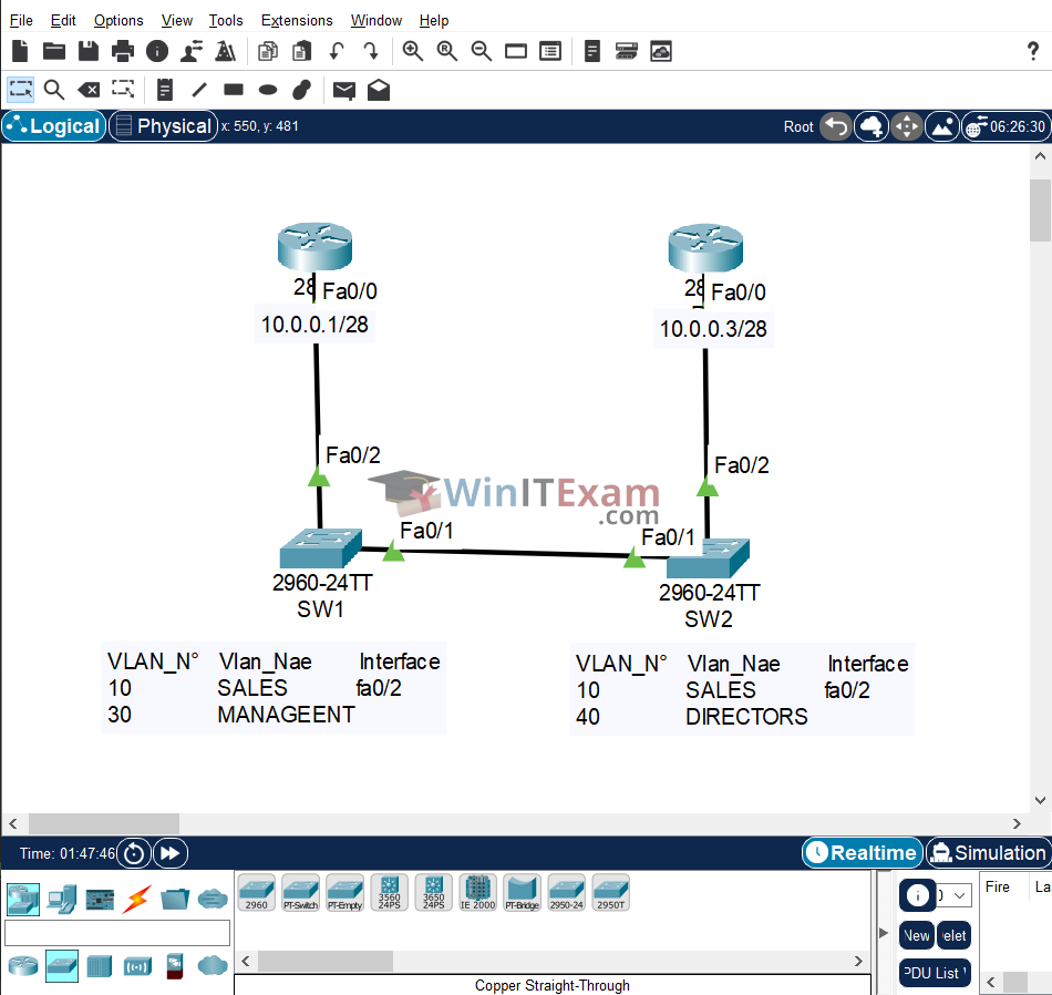
Lab Topology
Use the following topology to complete this lab exercise:
Task 1: Configure Hostname
Objective: Configure a hostname on switches 1 and 2 and routers 1 and 3 as illustrated in the topology.
Configuration Steps:
Switch#config t
Enter configuration commands, one per line.  End with CTRL/Z.
Switch(config)#hostname SW1
SW1(config)#

Switch#config t
Enter configuration commands, one per line.  End with CTRL/Z.
Switch(config)#hostname SW2
SW2(config)#

Router#config t
Enter configuration commands, one per line.  End with CTRL/Z.
Router(config)#hostname R1
R1(config)#

Router#config t
Enter configuration commands, one per line.  End with CTRL/Z.
Router(config)#hostname R3
R3(config)#
Task 2: Configure VTP Transparent Mode
Objective: Configure and verify SW1 and SW2 in VTP Transparent mode. Both switches should be in the VTP domain named CISCO. Switches must be in the same VTP domain to share VLAN information via a trunk.
Configuration Steps:
SW1#config t
Enter configuration commands, one per line.  End with CTRL/Z.
SW1(config)#vtp mode transparent
Setting device to VTP TRANSPARENT mode.
SW1(config)#vtp domain CISCO
Changing VTP domain name from NULL to CISCO
SW1(config)#end

SW1#show vtp status
VTP Version capable             : 1 to 2
VTP version running             : 1
VTP Domain Name                 : CISCO
VTP Pruning Mode                : Disabled
VTP Traps Generation            : Disabled
Device ID                       : 00D0.9774.C300
Configuration last modified by 0.0.0.0 at 0-0-00 00:00:00

Feature VLAN :
--------------
VTP Operating Mode                : Transparent
Maximum VLANs supported locally   : 255
Number of existing VLANs          : 5
Configuration Revision            : 0
MD5 digest                        : 0x1A 0xFC 0x64 0xDA 0x8E 0xA1 0x8A 0x3B
                                    0x47 0x97 0x87 0xB1 0x8B 0x59 0xE9 0x52

SW2#config t
Enter configuration commands, one per line.  End with CTRL/Z.
SW2(config)#vtp mode transparent
Setting device to VTP TRANSPARENT mode.
SW2(config)#vtp domain CISCO
Changing VTP domain name from NULL to CISCO
SW2(config)#end

SW2#show vtp status
VTP Version capable             : 1 to 2
VTP version running             : 1
VTP Domain Name                 : CISCO
VTP Pruning Mode                : Disabled
VTP Traps Generation            : Disabled
Device ID                       : 00E0.8FAE.5400
Configuration last modified by 0.0.0.0 at 0-0-00 00:00:00

Feature VLAN :
--------------
VTP Operating Mode                : Transparent
Maximum VLANs supported locally   : 255
Number of existing VLANs          : 5
Configuration Revision            : 0
MD5 digest                        : 0x1A 0xFC 0x64 0xDA 0x8E 0xA1 0x8A 0x3B
                                    0x47 0x97 0x87 0xB1 0x8B 0x59 0xE9 0x52
Task 3: Configure 802.1Q Trunk
Objective: Configure and verify FastEthernet0/1 between SW1 and SW2 as an 802.1Q trunk.
Note: Some Cisco switches default to 802.1Q trunking, but this is not the case for the 2960 Switch used in the exam.
Verification Commands:
SW1#config t
Enter configuration commands, one per line.  End with CTRL/Z.
SW1(config)#interface fastethernet0/1
SW1(config-if)#switchport mode trunk

SW2#config t
Enter configuration commands, one per line.  End with CTRL/Z.
SW2(config)#interface fastethernet0/1
SW2(config-if)#switchport mode trunk
Task 4: Configure and Verify VLANs
Objective: Configure and verify VLANs 10 and 30 on SW1 with the provided names. Assign FastEthernet0/2 on SW1 to VLAN 10 as an access port. Configure and verify VLANs 10 and 40 on SW2 with the provided names. Assign FastEthernet0/2 on SW2 to VLAN 10 as an access port.
Verification Commands:
SW1#config t
Enter configuration commands, one per line.  End with CTRL/Z.
SW1(config)#vlan 10
SW1(config-vlan)#name SALES
SW1(config-vlan)#exit
SW1(config)#vlan 30
SW1(config-vlan)#name MANAGEMENT
SW1(config-vlan)#exit
SW1(config)#interface fastethernet0/2
SW1(config-if)#switchport mode access
SW1(config-if)#switchport access vlan 10
SW1(config-if)#end
SW1#show vlan brief

VLAN Name                             Status    Ports
---- -------------------------------- --------- -------------------------------
1    default                          active    Fa0/3, Fa0/4, Fa0/5, Fa0/6
                                                Fa0/7, Fa0/8, Fa0/9, Fa0/10
                                                Fa0/11, Fa0/12, Fa0/13, Fa0/14
                                                Fa0/15, Fa0/16, Fa0/17, Fa0/18
                                                Fa0/19, Fa0/20, Fa0/21, Fa0/22
                                                Fa0/23, Fa0/24, Gig0/1, Gig0/2
1002 fddi-default                     active
1003 token-ring-default               active
1004 fddinet-default                  active
1005 trnet-default                    active
10 SALES                            active    Fa0/2
30 MANAGEMENT                       active

SW1#copy running-config startup-config

SW2#config t
Enter configuration commands, one per line.  End with CTRL/Z.
SW2(config)#vlan 10
SW2(config-vlan)#name SALES
SW2(config-vlan)#exit
SW2(config)#vlan 40
SW2(config-vlan)#name DIRECTORS
SW2(config-vlan)#exit
SW2(config)#interface fastethernet0/2
SW2(config-if)#switchport mode access
SW2(config-if)#switchport access vlan 10
SW2(config-if)#end
SW2#show vlan brief

VLAN Name                             Status    Ports
---- -------------------------------- --------- -------------------------------
1    default                          active    Fa0/3, Fa0/4, Fa0/5, Fa0/6
                                                Fa0/7, Fa0/8, Fa0/9, Fa0/10
                                                Fa0/11, Fa0/12, Fa0/13, Fa0/14
                                                Fa0/15, Fa0/16, Fa0/17, Fa0/18
                                                Fa0/19, Fa0/20, Fa0/21, Fa0/22
                                                Fa0/23, Fa0/24, Gig0/1, Gig0/2
1002 fddi-default                     active
1003 token-ring-default               active
1004 fddinet-default                  active
1005 trnet-default                    active
10 SALES                            active    Fa0/2
40 DIRECTORS                        active

SW2#copy running-config startup-config
Note: Default switches configured for VTP Transparent mode do not exchange VLAN information. You can see in the output above that VLAN 30 on SW1 is not propagated to SW2, and VLAN 40 on SW2 is not propagated to SW1. In Transparent mode, all VLANs must be manually configured on all switches.
Task 5: Configure and Verify IP Addresses
Objective: Configure R1 and R3 FastEthernet interfaces with the IP addresses 10.0.0.1/28 and 10.0.0.3/28, respectively. Test VLAN connectivity by pinging between R1 and R3.
Verification Commands:
R1#config t
Enter configuration commands, one per line.  End with CTRL/Z.
R1(config)#interface fastethernet0/0
R1(config-if)#ip address 10.0.0.1 255.255.255.240
R1(config-if)#no shutdown
R1(config-if)#end
R1#copy running-config startup-config

R3#config t
Enter configuration commands, one per line.  End with CTRL/Z.
R3(config)#interface fastethernet0/0
R3(config-if)#ip address 10.0.0.3 255.255.255.240
R3(config-if)#no shutdown
R3(config-if)#end
R3#copy running-config startup-config

R1#show ip interface brief
Interface              IP-Address      OK? Method Status                Protocol
FastEthernet0/0        10.0.0.1        YES manual up                    up
FastEthernet0/1        unassigned      YES unset  administratively down down
Vlan1                  unassigned      YES unset  administratively down down

R1#ping 10.0.0.3

Type escape sequence to abort.
Sending 5, 100-byte ICMP Echos to 10.0.0.3, timeout is 2 seconds:
.!!!!
Success rate is 80 percent (4/5), round-trip min/avg/max = 0/0/0 ms
NOTE: The first ping packet times out due to ARP resolution. Subsequent packets will be successful.

R3#show ip interface brief
Interface              IP-Address      OK? Method Status                Protocol
FastEthernet0/0        10.0.0.3        YES manual up                    up
FastEthernet0/1        unassigned      YES unset  administratively down down
Vlan1                  unassigned      YES unset  administratively down down

R3#ping 10.0.0.1
Type escape sequence to abort.
Sending 5, 100-byte ICMP Echos to 10.0.0.1, timeout is 2 seconds:
!!!!!
Success rate is 100 percent (5/5), round-trip min/avg/max = 0/0/0 ms
Cisco Packet Tracer file:
Load and open the .pkt Lab file in Cisco Packet Tracer from here: Configuring_VTP_Transparent_Mode.pkt